 EMAAR Energy

OH - HV - PINCE-BELL
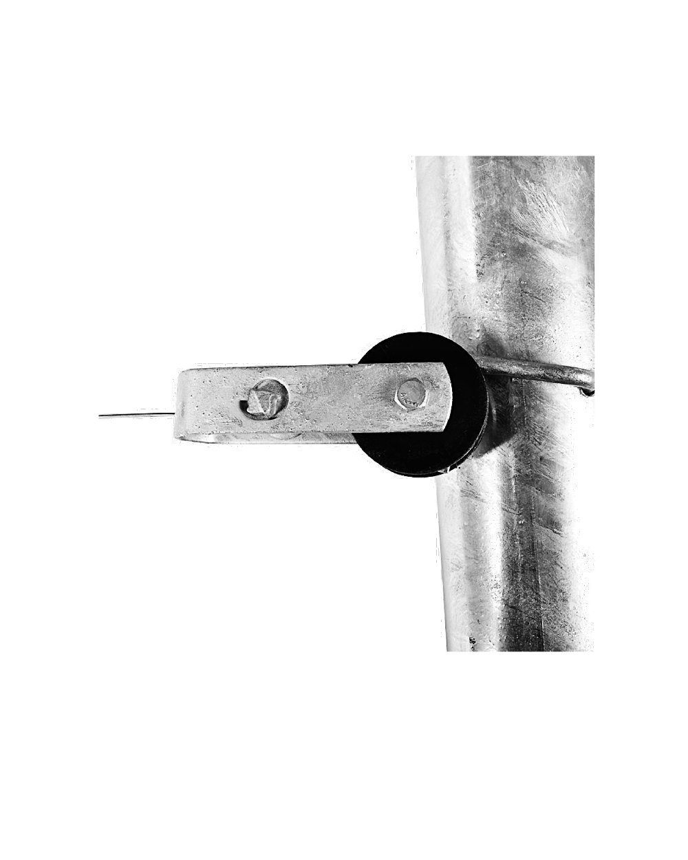
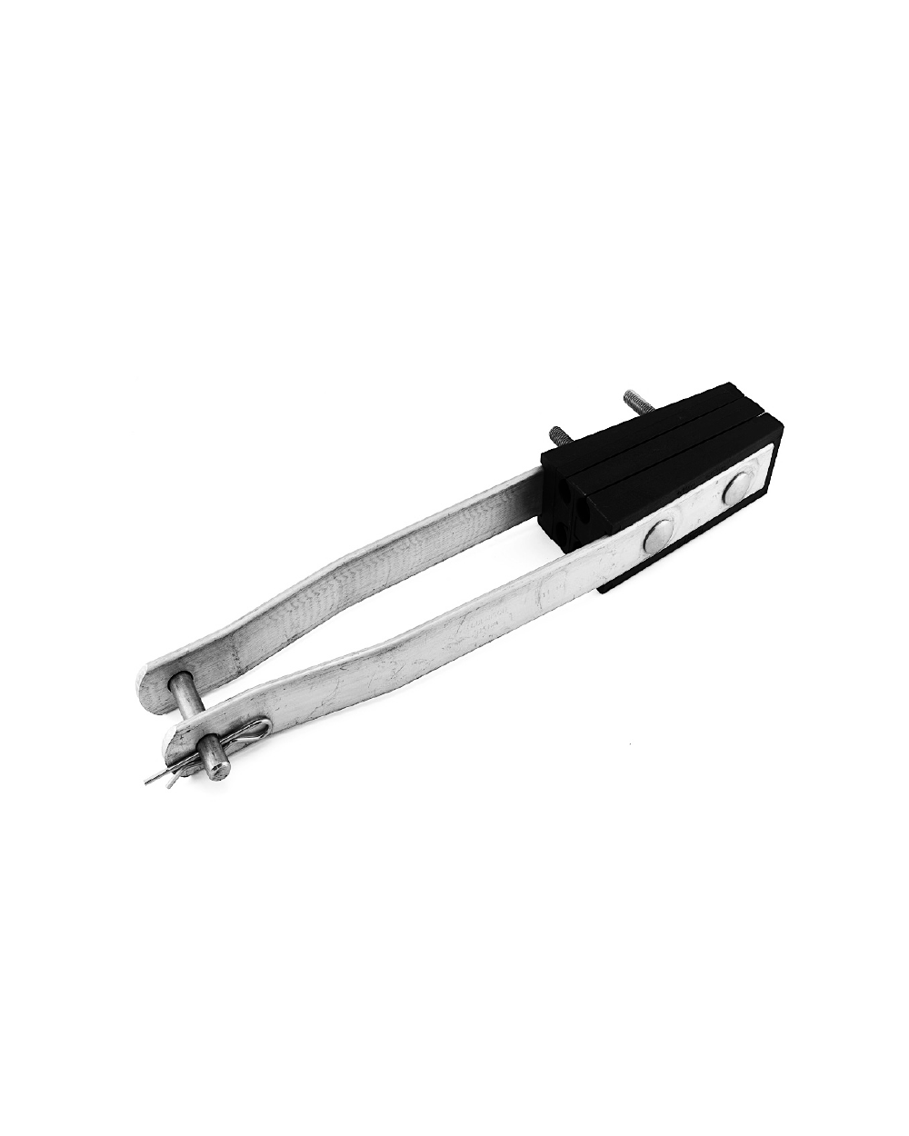
Vibration Damper – PINCE-BELL makes use of rotation and swing of the two-end hammer heads for generating friction damping force from the mutual slippage among the galvanized iron wire strands to consume the swing energy. It is adopted preformed rod structure in which the holding strength between the installation of vibration damper to preformed rods and the conductors evenly spread the distance from 30 to 60 cm on the length area, effectively protecting the conductor by avoiding the stress concentration of the latter. It is of good slippage and antivibration performance as well as superior installation of preformed rods guarantee sustainable, stable and reliable holding strength between the performed rods and the conductors while its highly efficient construction will be good for the convenient and reliable checkup. Its inertia and spiral elasticity can make the damping component generate relative displacement on the conductor swing, consuming vibration energy by effecting viscous damping phenomenon. The more the conductor swings, the more vibration damper consumes energy. Its installation shall take priority on its antinode; as its resonant frequency matches with the vibration frequency of conductor, the energy vibration damper consumes will be up to its maximum value.

Specifications
MATERIAL
Clamp: The bolted clamp permits easy installation on a wide range of conductor sizes. Aluminum clamping bolt ensures that damper clamp remains tight as conductor temperature changes with current load cycling.
Hardware: Aluminum/ Aluminum alloy
FEATURES
Maximum Protection From Wind- Induced Conductor Bending Strain
The four-resonant peaks include two separate cantilever response modes and two separate rotational response modes of the weight and messenger cable. These peaks also provide maximum energy dissipation to reduce strain over the entire spectrum of dangerous
wind velocities.
. Wide frequency response range optimizes protection of your system
. Large 19 strand wire and tight strand lay dissipate energy more efficiently
. Press fit permanent weight attachment technique assures long-term performance
. Contoured surfaces prevent corona discharge
Comprehensive Application Program for Optimum Performance
Provides precise selection and placement through our proprietary computer simulation
. Computer program based on a mathematical model verified by decades of laboratory testing and field vibration measurements
. Precisely identifies the vibration performance characteristics of transmission lines
. Determines dangerous tension levels for existing or proposed spans
. Identifies the frequency range, tension level and span lengths requiring damper protection
. Identifies proper damper placement for required vibration energy dissipation
Weights: Uniquely shaped so that the resonant peaks are effectively distributed over the desired frequency range. All weights are given a corrosion-resistant finish and have smooth surfaces and rounded edges to eliminate possible corona discharge.
* Notes: Dampers shall be located from the center of the damper clamp to either the dead end or the suspension support as shown above. The orientation of the damper weights along the conductor is optional. For convenience, orient the damper such that the clamp bolt head faces the installer. When only one damper is required per conductor per span, it can be installed at either span extremity when the support hardware is identical. When support hardware differs, place the damper at the suspension structure. When two dampers are required per conductor per span, the preferred placement is one at each span extremity.
CONDUCTOR’S APPLICATIONS
|
PRODUCT CODE |
AAC (mm2) |
ASCR (mm2) |
|
PINCE-BELL-1 |
35-70 |
16-70 |
|
PINCE-BELL-2 |
95-150 |
50-120 |
|
PINCE-BELL-3 |
120-185 |
70-150 |
|
PINCE-BELL-4 |
240-300 |
185-240 |
|
PINCE-BELL-5 |
350-400 |
300-350 |
|
PINCE-BELL-6 |
|
400-500 |
|
PINCE-BELL-7 |
35-70 |
16-70 |
|
PINCE-BELL-8 |
95-150 |
50-120 |
|
PINCE-BELL-9 |
120-185 |
70-150 |
|
PINCE-BELL-10 |
240-300 |
185-240 |
|
PINCE-BELL-11 |
350-400 |
300-350 |
|
PINCE-BELL-12 |
|
400-500 |
|
PINCE-BELL-13 |
35-70 |
16-70 |
|
PINCE-BELL-14 |
95-150 |
50-120 |
|
PINCE-BELL-15 |
120-185 |
70-150 |
|
PINCE-BELL-16 |
240-300 |
185-240 |
|
PINCE-BELL-17 |
350-400 |
300-350 |
|
PINCE-BELL-18 |
|
400-500 |
*Note: The products can be improved or modified based on specified requests of different market.
CONDUCTOR’S APPLICATIONS
|
PRODUCT CODE |
WEIGHT (kg) |
|
PINCE-BELL-1 |
2,3 |
|
PINCE-BELL-2 |
4,3 |
|
PINCE-BELL-3 |
4,4 |
|
PINCE-BELL-4 |
6,0 |
|
PINCE-BELL-5 |
8,0 |
|
PINCE-BELL-6 |
8,1 |
|
PINCE-BELL-7 |
2,5 |
|
PINCE-BELL-8 |
4,7 |
|
PINCE-BELL-9 |
4,8 |
|
PINCE-BELL-10 |
6,6 |
|
PINCE-BELL-11 |
8,8 |
|
PINCE-BELL-12 |
8,9 |
|
PINCE-BELL-13 |
2,9 |
|
PINCE-BELL-14 |
5,4 |
|
PINCE-BELL-15 |
5,5 |
|
PINCE-BELL-16 |
7,5 |
|
PINCE-BELL-17 |
10,0 |
|
PINCE-BELL-18 |
10,1 |
*Note: The products can be improved or modified based on specified requests of different market.
SAFETY CONSIDERATION
1. This product is intended for use by trained craftspeople only. This product SHOULD NOT BE USED by anyone who is not familiar with and trained in the use of it.
2. When working in the area of energized lines with this product, EXTRA CARE should be taken to prevent accidental electrical contact.
3. For PROPER PERFORMANCE and PERSONAL SAFETY be sure to select the proper size EMAAR product before application.
4. EMAAR products are precision devices. To insure proper performance, they should be stored in cartons under cover and handled carefully.
Related Products
OH - ABC - Clamp - PINCE-CAKE
ABC Insulated Tensioner
OH - ABC - Clamp - PINCE-OCTOx
ABC Bolted-Wedge Anchoring Clamp
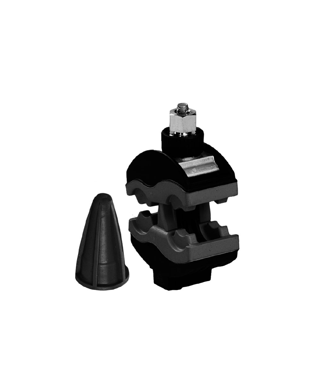
OH - ABC - Clamp - PINCE-VAMP
ABC Insulation Piercing Connector
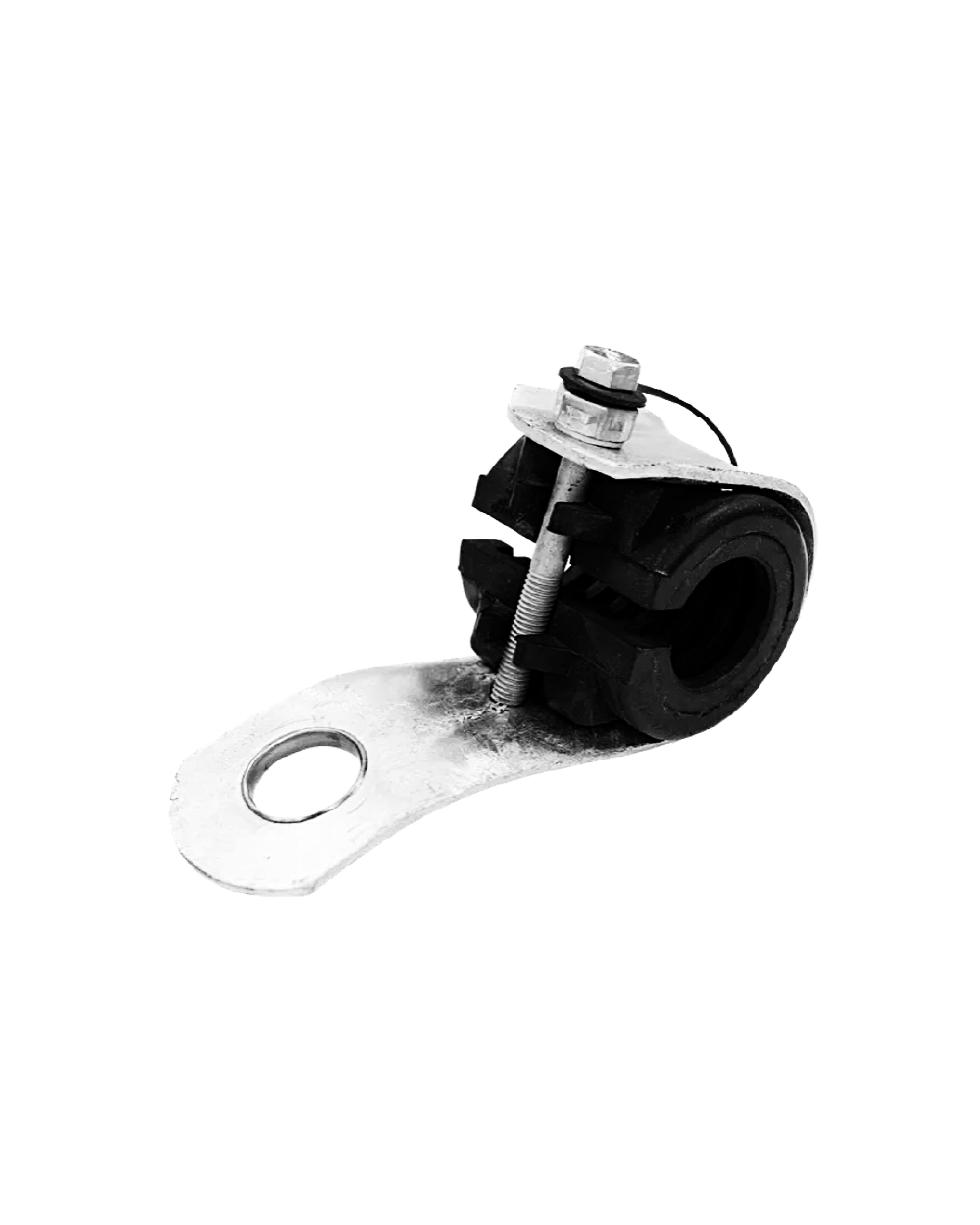
OH - ABC - Clamp - PINCE-WORM
ABC Suspension Clamp